Author: Noah Gilbertson
Presented by: G Standard Industrial
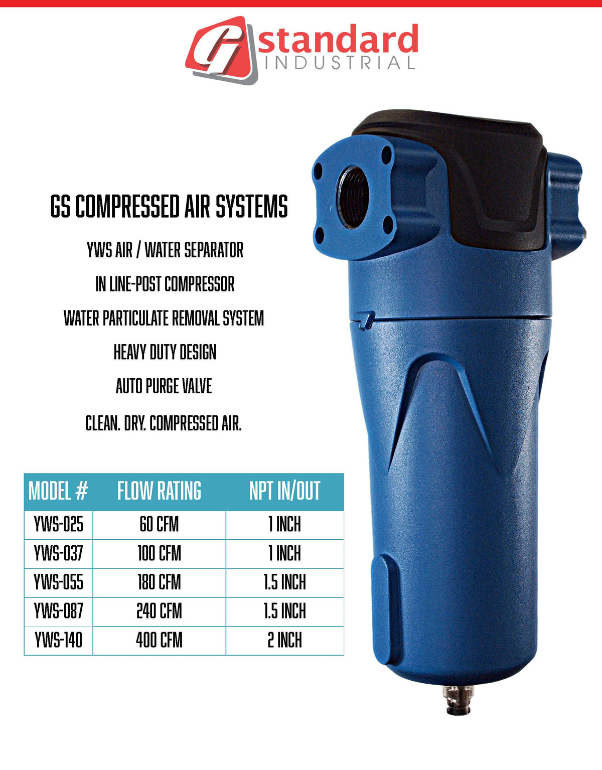
Accurately calculating your facility's air demand is the foundational step in designing an efficient and reliable compressed air system. Getting this wrong leads to poor performance, high energy costs, and premature equipment failure. This guide provides a clear methodology for determining your true CFM and PSI requirements.
Part 1: Calculating Required CFM (Flow Rate)
CFM (Cubic Feet per Minute) is a measure of volumetric flow rate—how much air your tools and equipment consume.
The Step-by-Step Calculation Method:
-
Create an Equipment Inventory: List every machine, tool, and process that uses compressed air in your facility. Don't forget drains, air blows, and other often-overlooked consumers.
-
Determine Individual CFM Requirements: For each item on your list, find its CFM consumption. This information is usually stamped on the tool itself or available in its manual. Crucially, note if the value is CFM or SCFM. SCFM (Standard CFM) is referenced to a standard condition and is the more accurate unit for sizing.
-
Account for Duty Cycle: Most tools do not run continuously. A grinder might be in use 50% of the time in a given cycle. Multiply each tool's CFM by its duty cycle (expressed as a decimal).
-
Example: A grinder rated for 20 CFM with a 50% duty cycle: 20 CFM * 0.50 = 10 CFM average consumption.
-
-
Calculate Simultaneous Usage: You must estimate how many of these tools will be used at the same time. There are two ways to do this:
-
Theoretical Maximum: Sum the CFM of every single tool. This is overly conservative and will lead to a massively oversized system.
-
Usage Factor (Recommended): Apply a realistic "usage factor" (F) to the total CFM. This is an engineering estimate based on your production knowledge. A common starting point is 0.6 to 0.8 (60-80% of all tools running simultaneously), but this varies widely by facility.
-
-
Add a Safety Margin: Add a margin of 10-25% to your final calculated CFM to account for future expansion, air leaks, and calculation uncertainties.
The Formula:
Total Required CFM = (∑(Tool CFM * Duty Cycle)) * Usage Factor (F) + Safety Margin
Part 2: Determining Required PSI (Pressure)
PSI (Pounds per Square Inch) is a measure of pressure—the "force" behind the air.
-
Identify the Highest Pressure Tool: Find the tool or machine in your inventory that requires the highest operating pressure. This information is also found on the tool or in its manual.
-
Account for System Pressure Drop: Compressed air loses pressure as it travels through dryers, filters, piping, hose, and fittings. This is called pressure drop.
-
A well-designed system will have a pressure drop of ~10-15 psi from the compressor discharge to the point of use.
-
A poorly designed system can have a drop of 30 psi or more.
-
-
Calculate the Required Discharge Pressure:
-
Required Compressor PSI = (Highest Tool PSI) + (Total System Pressure Drop)
-
Example: If your highest-pressure tool needs 90 psi and your system pressure drop is estimated at 15 psi, you need a compressor that can generate at least 105 PSI at its discharge.
-
Practical Method: The "Bag Test" for Existing Systems
For facilities with an existing but undersized system, you can empirically measure air consumption.
-
Time How Long It Takes to Fill a Tank: Use a stopwatch to time how long it takes for your compressor to fill its receiver tank from a lower pressure cut-in point to a higher cut-out point.
-
Use the Formula:
CFM = (Gallons of Tank) / (Time in Seconds to Fill) * (P2 - P1) / 14.7 * (60 / 7.48)-
Where P2 is the cut-out pressure (psig) and P1 is the cut-in pressure (psig).
-
This calculates the compressor's actual output, which can be compared to your theoretical demand.
-
Conclusion:
While these calculations can be done manually, for complex systems, a professional air audit using data loggers is highly recommended. G Standard Industrial offers this service to precisely measure your facility's air demand profile, ensuring the rotary screw compressor and support system we recommend are perfectly sized for maximum efficiency and minimum total cost of ownership.
Sources for this Article:
-
U.S. Department of Energy. (2004). Improving Compressed Air System Performance: A Sourcebook for Industry. "Chapter 3: Compressed Air System Components" and "Appendix A: Compressed Air Measurement." DOE/GO-102004-1826. Retrieved from https://www.energy.gov/eere/amo/downloads/improving-compressed-air-system-performance-sourcebook-industry
-
Compressed Air and Gas Institute (CAGI). (n.d.). Compressed Air System Basics: Sizing Your System. Retrieved from https://www.cagi.org/
-
National Institute of Standards and Technology (NIST). (2002). Guidelines for the Use of International System of Units (SI). NIST Special Publication 811. (For reference on SCFM vs. CFM). Retrieved from https://www.nist.gov/pml/special-publication-811
0 comments